Induction timer is a compact instrument capable of measuring induction time, t, which is defined as the minimum time required for film thinning, film rupture and three-phase contact line expansion.
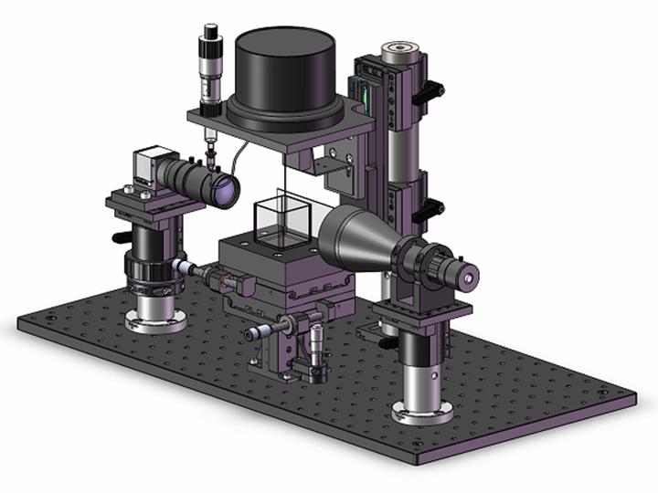
Figure 1 is a 3D view of the instrument, comprising a gas bubble or liquid drop generation system, an advanced image system including a high-speed camera, a regular (or telecentric) zoom lens and a telecentric illuminator, a sample stage with a three-way manual translation, a precision micro-displacement sensor, a multifunctional software, Floatimer, that controls all motors, monitors the displacement sensor’s feedback, records and analyzes images to make measurements. With the gas bubble or liquid drop generation system, an air bubble of controllable size can be generated at the end of a capillary tube using a micro-syringe. The advanced image system is used to assist in viewing the precise positioning and contacting process between the air bubble and solids particles, and to provide high quality images for edge detection and digital image processing.

Induction time measurement
A layer of testing solid particles is placed in a testing liquid (or solution) held in a square glass cell, a small air bubble is generated at the tip of the glass capillary using the gas bubble generation system. Induction time measurement comprises using a controller to send a square (or a ladder) wave instruction with a preset time period, tn, from the computer to an amplifier enclosed in the control box and observing whether attachment can be established between the air bubble and the solid particles in the testing liquid, the amplifier then applies a current to the drive, whereby to move the air bubble down to and make contact with the particle bed for the preset time period, tn, then retract to its original place as shown in Fig. 3(a). Induction time, tind, is defined as the minimum contact time required to establish attachment between the air bubble and the solid particles. When a few solid particles are observed at the bottom of the air bubble after the air bubble retracts to its original place, the attachment is established, the preset contact time, tn, is considered longer than the induction time, tind, a shorter time, tn-1, shall be preset and do another try. Contrarily, when no solid particle is observed at the bottom of the air bubble after the air bubble retracts to its original place, the attachment is not established, the preset contact time (tn) is considered shorter than the induction time (tind), a longer time, tn+1, shall be preset and another try shall be carried out. This testing procedure shall be performed as many times as possible till the incremental value (tn+1 – tn) is close or equal to the decremental value (tn – tn-1) and falls an acceptable error range, then the, tn, is considered as its induction time, tind.
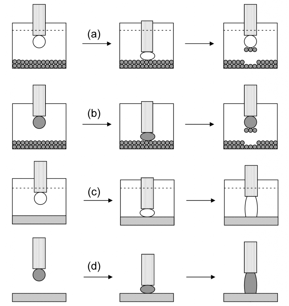
The induction time of solid-air bubble can be measured either using an air bubble to attach a solid particle bed in a testing liquid as shown in Fig. 3(a) or using a drop of the testing liquid to attach the solid particles bed exposing in the air directly as shown in Fig. 3(b). The method 3(a) involves the liquid receding process (solid-air interface replacing solid-liquid interface), hence provides a receding induction time, treceding, while the method 3(b) involves the liquid advancing process (solid-liquid interface replacing solid-air interface), hence provides an advancing induction time, tadvancing.
The induction time of solid-air bubble in the testing liquid can also be measured using a solid substrate with a flat surface as shown in Fig. 3(c), attachment between the solid surface and the air bubble is believed to have been established when the air bubble is sticking on the solid surface after the capillary tube retracts to its original place. The induction time of solid-air bubble in the testing liquid can also be measured using a drop of the testing liquid to contact the solid substrate in the air environment as shown in Fig. 3(d), attachment between the solid surface and the testing liquid drop is believed to have been established when the drop of the testing liquid is sticking on the solid surface after the capillary tube retracts to its original place. The method shown in Fig. 3(c) provides a receding induction time, while the method shown in Fig. 3(d) provides an advancing induction time.
Application
This refined induction timer can be used for studying air bubble–particle, oily bubble-particle, air bubble–bitumen as well as bitumen–particle attachment and bitumen–bitumen coalescence. The induction timer is suitable to measure induction time greater than 10 ms accurately. It can also measure induction time within 3-9 ms at reduced accuracy. Effects of temperature, pH and water chemistry on induction time can be studied. The shorter the induction time is, the higher the flotation efficiency at a flotation operating condition.
Specifications
- Model: 2020EZ
- Induction time:> 10 ms, ± 1 ms
- Operating temperature: Ambient – 70 ºC, ± 0.1 ºC
- Translation stage travel distance:Manual XY-move 50 mm, Z-move 12.7 mm; motorized Z-move 50 mm
- Stage travel resolution:Coarse-18TPI, Fine-100TPI, Motorized-0.1 microns
- Micro-displacement resolution:5 microns within 4 mm
- Software driver:Floatimer 2020 Ver.10,Win 10
- Camera: CMOS 1/2″, color, 200 fps, video resolution 1280 X 1024, USB 3.0
- Lens: 0.47 – 3.0X telecentric, zoom, Iris and focus controls, inline illumination
- Light source: LED light source with intensity control , flexible dual guide,
- Illumination: back-light illuminator with Iris control
- Capillary size:0.66-0.70 mm ID X 10 cm
- Power:85-240 VAC, 300 W
- Dimension (Main body):610 mm(L) X 305 mm(W) X 330 mm(H)
- Dimension (Control box) :255 mm (L) X 230 mm (H) X 305 mm (D)
- Computer included
- CPU: ≥ 1.5 Ghz
- Hard disk: ≥ 500 GB
- Memory: ≥ 8 G
- Operating system: Win 10
- USB2.0 port: 2; USB 3.0 port: 1