1. Background
Air-particle or air-bitumen attachment is an essential step for a successful flotation and is strongly dependent on the chemistry of a flotation system. In a broader sense, induction time is defined as the minimum times required for film thinning, film rupture and three-phase contact line expansion. Since it is fairly difficult to accurately measure these times separately, in practice, they have been measured collectively and referred to as the induction time. The induction time plays a critical role in flotation. Under a given hydrodynamic condition, the shorter the induction time is, the higher the flotation recovery.
Flotation is an important separation technique that has been used for a century in the mining industry for the recovery of valuable minerals. Flotation has also been adopted by other industries, e.g. the pulp and paper industry for the separation of ink, toner, and other unwanted contaminants from wood fibers during waste paper recycling operations. In Canadian oil sands operations, flotation has been used to recover bitumen from oil sands.
Theoretical studies on film thinning, film rupture and three-phase contact line also showed that the induction time measured by moving an air bubble toward and then away from a mineral bed in a liquid is a function of physical properties of the solid particles (e.g. size, density and contact angle), physical properties of the liquid (viscosity, density and surface tension) and the three-phase contact line tension. The key factors controlling the attachment of air bubble-solid particles in a liquid are surface and interfacial properties of the intervening phases, e.g. surface energy of the solid, surface tension of the liquid, interfacial tension of the solid-liquid as well as contact angle of the liquid contacting the solid surface. Only the contact angle and surface tension are directly measurable, all other surface and interfacial properties are derived from these two properties. It is desirable to have an instrument capable of measuring induction time, surface and interfacial properties.
2. Working principle of the instrument
A schematic of the induction timer is shown in Figure 1. A speaker is used as a power drive. The movement of an air bubble is controlled by the speaker’s diaphragm via a capillary tube (0.6-0.7 mm in diameter). One end of the capillary tube is attached to the diaphragm with the other end holding the air bubble. The air bubble of controllable size is generated at the end of the capillary tube by a Gilmont micro-syringe. A lens and a high speed CCD camera are used to assist viewing the precise positioning and contacting process between the air bubble and solids particles, a pressed plate specimen or a bitumen-coated plate.
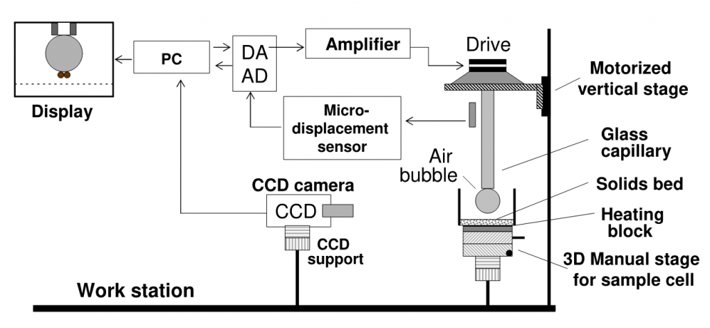
An amplifier interfaced with a computer is used as a power source to drive the speaker and hence the air bubble that is attached to the capillary tube. A micro-displacement sensor is mounted approximately 4 mm away from the reflection disk attached to the speaker’s diaphragm to detect the actual displacement of the speaker’s diaphragm. The duration and the amplitude of the displacement can be set at 0.1 ms and 5 μm resolution, respectively. A data acquisition device is used for measurement control. A software driver controls the whole system, which allows instructions to be sent to the controller and signals to be received from the displacement sensor in real time. The video signal from the camera is captured into computer via an USB 3.0 port and displayed on computer display. The response signal from the micro-displacement sensor can be saved to hard disk for the analysis of the speaker diaphragm’s moving profile, which is related to air bubble approaching velocity toward a particle bed, a pressed plate specimen or a coated plate with different values of hydrophobicity.